How to Syncronize Spi Read an Write
This post describes how the SPI interface works, with particular reference to the Arduino Uno which is based on the ATmega328P microprocessor scrap. A lot of the details however volition exist of more than general involvement.
SPI is used to send series information from a microprocessor to another 1, or a peripheral, for example an LCD display, a temperature sensor, a memory (SD) chip, and then on.
More than information almost SPI at:
http://en.wikipedia.org/wiki/Serial_Peripheral_Interface_Bus
More information about the Arduino SPI interface at:
http://arduino.cc/en/Reference/SPI
Other protocols
- Summary of protocols: http://www.gammon.com.au/forum/?id=10918
- ane-wire: http://www.gammon.com.au/forum/?id=10902
- Parallel interface: http://world wide web.gammon.com.au/forum/?id=10903
- Two-wire (I2C): http://www.gammon.com.au/i2c
- Serial (async): http://www.gammon.com.au/forum/?id=10894
Sending data
Allow'due south commencement with an prototype - this is a screenshot taken with a logic analyser. It shows the 3-character sequence "Fab" being sent from the Arduino.
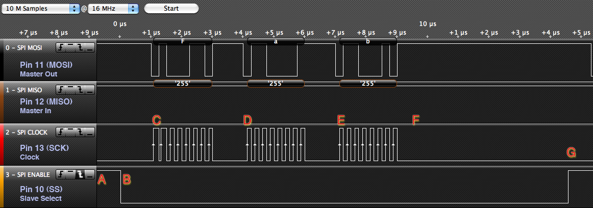
I put a trigger on the SS (Slave Select) pin and so that the logic analyser would start analysing from when the sequence started.
From the above graphic note the following points of involvement:
- A - no data (SS is high, clock is low)
- B - SS taken low to enable the slave (peripheral). At this point the slave should set to transfer data by setting the MOSI (master out, slave in) line, and the SCK (serial clock) as inputs, and the MISO (master in, slave out) every bit an output. The slave can at present prepare to notice clock pulses on the SCK line.
- C - Outset character arrives (the letter "F" or 0x46 or 0b01000110). For each of the 8 $.25 the SCK (clock) line is briefly brought high, and and then low over again. This tells the slave to read the information on the MOSI line. Besides the slave can place data on the MISO line for the main to simultaneously read in.
- D - The letter "a" arrives
- Due east - The letter "b" arrives
- F - "No data" afterward "Fab" - notwithstanding the SS is still enabled.
- Thousand - SS taken high to indicate stop of the sequence of data. At this stage the slave should release the MISO line (configure it every bit an input, or "high impedance"). Also the slave should ignore any clock pulses now (they may be for a different peripheral).
The lawmaking to produce this (in Arduino's C++ language) was:
// Written by Nick Gammon // January 2011 #include <SPI.h> void setup (void) { } void loop (void) { digitalWrite(SS, HIGH); // ensure SS stays high // Put SCK, MOSI, SS pins into output mode // also put SCK, MOSI into Depression land, and SS into HIGH state. // And so put SPI hardware into Main style and plough SPI on SPI.begin (); filibuster (5000); // 5 seconds delay to start logic analyser. char c; // enable Slave Select digitalWrite(SS, LOW); // SS is pin 10 // ship exam cord for (const char * p = "Fab" ; c = *p; p++) SPI.transfer (c); // disable Slave Select digitalWrite(SS, High); // turn SPI hardware off SPI.finish (); while (i); //loop }
More detail for the first character (the alphabetic character "F" or 0x46 or 0b01000110) can be seen hither:

Notice how for each bit (starting with the almost significant scrap) the MOSI line is first inverse to the correct state (0 or 1) so the SCK (clock) line is pulsed to bespeak that the data should be read.
Sending and receiving data
The adjacent graphic, taken while sending information to an Ethernet card, shows how both MOSI and MISO lines tin be exchanging data simultaneously:

Basically, while the master hardware is clocking out bits on the MOSI line (main out, slave in) it is too clocking in $.25 on the MISO (principal in, slave out). Effectively, during ane character time, it both sends and receives 1 byte. Hence the name of the part SPI.transfer.
The code that produced the above might take looked like:
char a, b; a = SPI.transfer (four); // a is now 1 b = SPI.transfer (3); // b is now 2
Timing
Every bit y'all tin see from the Logic analyser timing, each byte seems to take near 3 microseconds to be sent, so that means you lot could transport 333,333 bytes in ane 2d, effectively being 325.5 Kbytes/s (333333/1024).
The clock pulses are 0.25 microseconds autonomously (0.125 microseconds on and 0.125 microseconds off). Effectively this means it is clocking at four MHz.
[EDIT] However see below ("SPI speeds") for a more than detailed analysis. In detail, rates of 888,888 bytes per second are theoretically achievable (868 Kbytes/s). Likewise you tin boring SPI down if the receiving end operates more slowly or needs time to procedure the information.
Slave Select
There is a bit of confusion about the Slave Select pivot. This is because the SPI hardware tin be used to communicate with a number of slaves at once. The way this is washed is to tie the SCK, MISO and MISO lines together (for each slave) and take a dissever SS (slave select) line for each slave. This way you only demand 3 wires (plus basis) in total, plus 1 slave select for each slave.
Thus, slaves should let each of the lines float (every bit inputs) unless their slave select is taken low. Then, and merely then, should they configure their MISO line (principal in, slave out) to exist an output, so they can send information dorsum to the master.
Pin 10 of the Arduino is the SS line - and so does this hateful you lot have to employ information technology for the peripheral SS line? Or should it be kept loftier? The reply (from the Atmega documentation) is that the SS line (pin 10) must exist configured as an output (regardless of what value is on it). If configured as an output the Arduino ignores the value on that line, and thus the SPI hardware will not be put into slave manner.
Since the value on pin x is ignored, providing it is ready as an output, and then it can also be used as the SS line for your kickoff, or only, slave. You could then apply other pins (eg. 5, 6, 7, 8, 9) to control other slaves.
Protocols
The SPI spec does non specify protocols as such, so information technology is up to individual master/slave pairings to agree on what the data means. Whilst y'all can ship and receive bytes simultaneously, the received byte cannot exist a directly response to the sent byte (every bit they are being assembled simultaneously). For example, in the graphic above, the slave is not replying with a 1 to the transfer of 4, because it doesn't know information technology has received 4 earlier it has already sent 1.
And then it would be more than logical for one end to send a request (eg. 4 might hateful "listing the disk directory") so do transfers (maybe just sending zeros outwards) until it receives a complete response. The response might finish with a newline, or 0x00 character.
You lot also don't necessarily know if yous even accept a peripheral attached. One style might be to send out a "query", like this:
SPI.transfer (0xCD); // are you lot there? byte x = SPI.transfer (0); // go response if (x == 0xEF) { // peripheral is live }
This case asks the slave to reply with 0xEF if it receives 0xCD - this presumably wouldn't happen if the wires were not connected to annihilation. This could be used to verify that the slave actually was there and "alive".
Modes
For maximum flexibility with various slaves, the SPI protocol allows for variations on the polarity of the clock pulses. CPOL is clock polarity, and CPHA is clock phase.
- Mode 0 (the default) - clock is normally low (CPOL = 0), and the information is sampled on the transition from low to high (leading edge) (CPHA = 0)
- Way 1 - clock is normally low (CPOL = 0), and the data is sampled on the transition from loftier to depression (trailing border) (CPHA = one)
- Way 2 - clock is normally loftier (CPOL = 1), and the data is sampled on the transition from high to low (leading edge) (CPHA = 0)
- Mode 3 - clock is normally high (CPOL = 1), and the data is sampled on the transition from low to high (trailing edge) (CPHA = i)
Style 0

Mode 1

Manner 2

Style 3

Example lawmaking to modify mode:
SPI.setDataMode (SPI_MODE3);
There is too a DORD (data guild) flag. The normal club is most pregnant bit get-go (as above) but the alternate guild is to the lowest degree pregnant bit first.
Arduino Library
The Arduino evolution kit comes with an SPI library. To use it you just demand to include information technology, like this:
#include <SPI.h>
This gives you an SPIClass, and an instance of that class called SPI in SPI.cpp.
To condition the hardware yous telephone call SPI.brainstorm () which configures the SPI pins (SCK, MOSI, SS) as outputs. Information technology sets SCK and MOSI low, and SS loftier. It then enables SPI way with the hardware in "master" mode. This has the side-issue of setting MISO as an input.
If you need to modify the way or scrap order you have the functions SPI.setDataMode and SPI.setBitOrder. Usually yous wouldn't have to.
The function SPI.transfer does the actual transferring of bytes. It is up to you lot to set SS low at an appropriate time (this may or may not be pin 10 as described above). When finished call SPI.end () to plow the hardware SPI off.
Pinouts on the Arduino Uno

Pinouts on the Arduino Mega2560
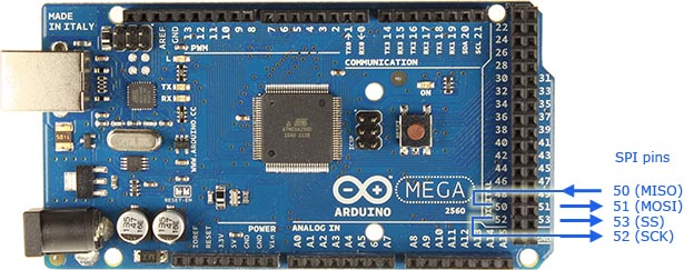
On the Arduino Mega, the pins are fifty (MISO), 51 (MOSI), 52 (SCK), and 53 (SS).
Pinouts using the ICSP header
You can too connect to the SPI pins (except SS) past using the ICSP header (on both the Uno and the Mega2560):

[EDIT] Modified 8th July 2012 to add screenshots of logic analyzer output of the diverse clock modes.
- Nick Gammon
www.gammon.com.au, www.mushclient.com
Source: https://gammon.com.au/spi
0 Response to "How to Syncronize Spi Read an Write"
Post a Comment